Installation
Installation
Your PROCON pump is a precision-built piece of equipment. Handle it carefully. PROCON pumps should be installed only by qualified technicians.
NOTICE When you install your pump, follow these guidelines:
- Do not hammer or mishandle your pump.
- Keep all foreign materials out of your pump.
- Never vise or grip the round body portion of the pump housing. Grip only the square inlet/outlet bosses when you install fittings. Always support the pump when you install fittings to avoid bending the V-band clamp even if the pump is already mounted to the motor.
- Make sure the power is off before working with an electric motor. If possible, lock out the power at a disconnect.
- Make sure you have an adequate, well-lit work space and use the correct tools.
- Do not use any components that are damaged or deformed. You should not have to force any parts together. If you receive parts that are damaged or deformed, call your PROCON factory representative.
We test every PROCON pump at the factory for pressure and flow. If the pump has a relief valve, we set it to your specifications.
CAUTION Do not tamper with the relief valve on your pump. If you think the relief valve needs to be reset, contact your PROCON factory representative.
We make every effort to ensure that your pump is of the highest quality. To get the most out of your pump, read and follow these instructions carefully.
Before you install your pump, you must carefully unpack the pump and examine and prepare it to be installed. Follow these steps for all types of motors.
Notice
Do not exchange one pump model for another. Pumps are carefully engineered to meet specific requirements and flow rates.
All pumps within a series have the same housing. They make look alike, but they perform differently. Check the model number to make sure you have the correct pump before you install it.
Using the wrong pump may damage your pump, system, or electric motor.
Step 1. Take the pump out of the shipping container
- Do not remove the shipping plugs from the port until the fittings are ready to be installed. This will keep debris out of the pump.
- If the pump has a shaft coupling, remove the coupling and discard the foam shipping strip. Reinsert the coupling.
- Be careful when handling the pump. If you mishandle the pump, especially the shaft end, you can disrupt or damage internal clearances and impair performance of your pump.
Step 2. Examine the mounting surfaces
- Carefully remove any burrs or raised metal which may have occurred during unpacking and handling to make sure the pump will sit and be aligned properly.
Step 3. Ready to Mount
- Now you are ready to mount the pump to a motor. PROCON Rotary Vane Pumps work with two types of electric motors. Follow the steps for the type of motor you are using.
NOTICE Do not exchange one pump model for another. Pumps are carefully engineered to meet specific requirements and flow rates.
All pumps within a series have the same housing. They may look alike, but they perform differently. Check the model number to make sure you have the correct pump before you install it.
Using the wrong pump may damage your pump, system, or electric motor.
PROCON Rotary Vane Pumps can be mounted to two types of electric motors, a carbonator style motor (NEMA 48YZ frame) and a C-frame motor (NEMA 56C frame).
Pump applications that require a motor of up to 0.75 horsepower, open drip proof construction and single phase power can be close-coupled to NEMA 48YZ frame, carbonator style motors. Use a V-band clamp to secure the mounting. You do not need to use any additional couplings or adapters.
Pump applications that require a motor greater than 0.75 horsepower, TEFC construction or 3 phase power can be mounted to NEMA 56C frame motors. You will need an aluminum C-face adapter and shaft coupling to mount your pump to a NEMA 56C frame motor. The adapter and coupling are available from PROCON.
Besides PROCON, motors are available from your local electric motor distributor. NEMA 48YZ and NEMA 56C frame motors are available in 50 and 60 hertz as well as high and low voltage. NEMA 56C frames are available in single and 3 phase models as well as open drop proof, TEFC, and explosion proof versions from 0.25 to 3 horsepower. NEMA 48YZ frames are limited to single phase, open drop construction from 0.25 to 0.75 horsepower.
Mag Drive Vane, Micro Vane and Gear Pumps are factory installed pump & motor assembly. Do not remove or change motors without factory’s permission as they are specific to the application. This also voids the warranty.
Mounting on a 56C Frame Motor
Your PROCON pump is a precision-built piece of equipment. Handle it carefully. PROCON pumps should be installed only by qualified technicians.
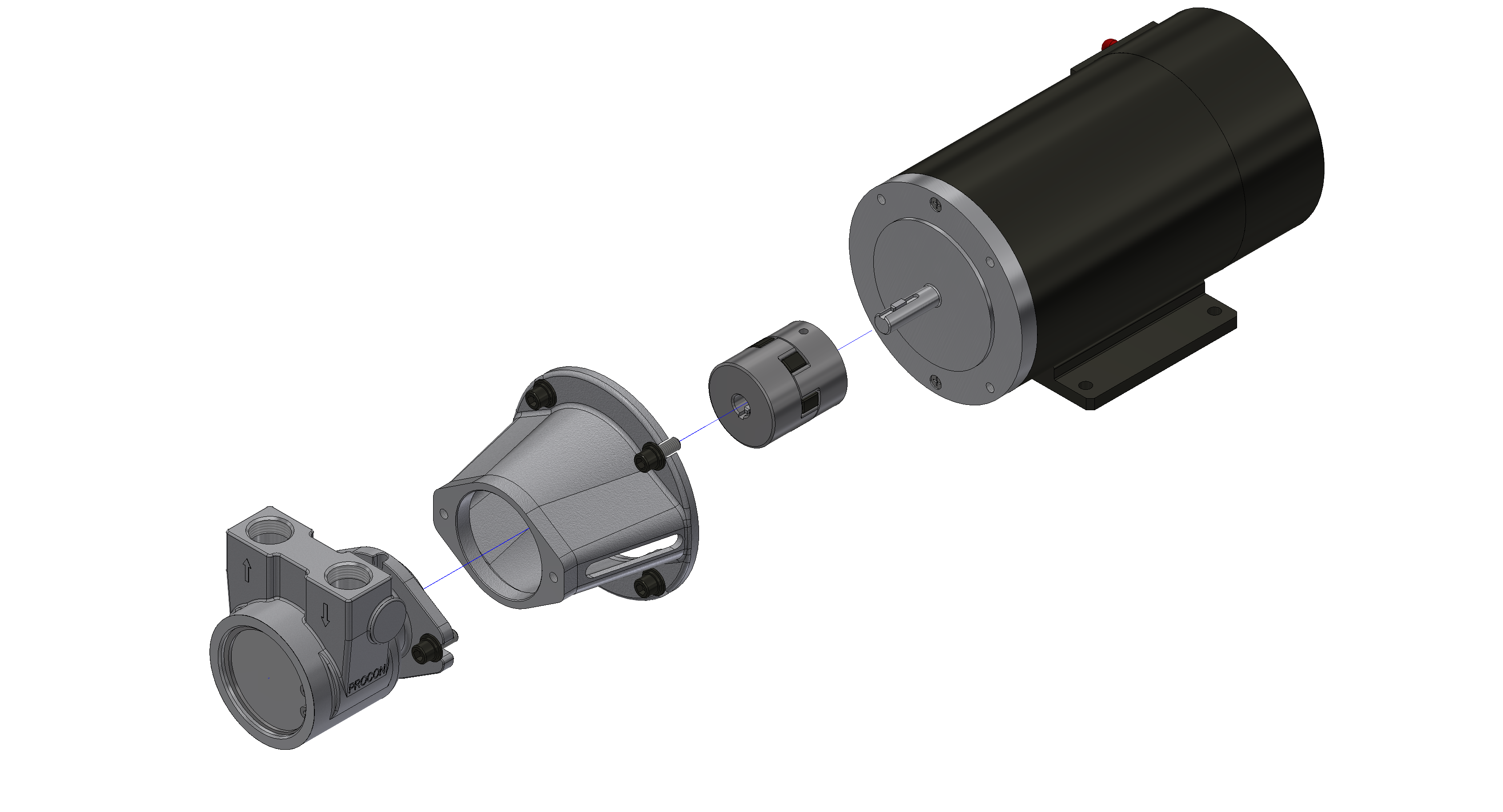
NOTICE You should have these parts:
- Bolt-on pump
- Motor adapter
- 3-piece drive shaft coupling
- 56C frame motor
PROCON bolt-on style pump mounted to a 56C frame motor with coupling.
Correctly assembling the coupling and the adapter, and mounting the pump is a trial and error process. You may have to try several times before you get it right. Follow these steps after you have examined your pump.
1. Mount the drive shaft coupling
- Make sure the motor is electrically disconnected and cannot accidentally turn on.
- Mount the half of the coupling for the motor onto the motor shaft and tighten the set screw.
- Insert the elastomer piece onto the motor piece.
- Mount the half of the coupling for the pump onto the pump shaft, but do not tighten the set screw.
- Make sure the coupling slides easily onto the pump and the motor shaft, do not force it.
- Make sure the shaft does not protrude into the space occupied by the elastomer piece. Series 6 pumps require a shaft key.
2. Mount the motor adapter - Use four 3/8 inch dia. by 1 inch long bolts (16 threads/inch) and lock washers. - Rotate the pump to orient the inlet/outlet ports.
3. Trial mount the pump onto the motor adapter while engaging the coupling pieces
4. Check to make sure the coupling is properly engaged
5. Tighten the set screw on the pump
6. Check your assembly - The elastomer coupling piece should have about 1/16 inch of play between the two metal pieces. - If it does not, repeat steps 1-5 until corrected.
7. Fasten the pump to the adapter - Use three 1/4 inch dia. by 3/4 inch bolts (20 threads/inch) and lock washers. For series 6 pumps, use two 3/8 inch dia. by 1 inch bolts (16 threads/inch).
8. Make sure the motor rotates correctly - Must correspond to the arrows on the nameplate
Mounting on a 48YZ Frame Motor

Your PROCON pump is a precision-built piece of equipment. Handle it carefully. PROCON pumps should be installed only by qualified technicians.
NOTICE You should have these parts:
- Clamp-on pump
- V-band Clamp
- 48YZ frame motor
PROCON clamp-on style pump mounted to a carbonator motor with clamp
After you have examined your pump for damages, follow these steps:
1. Make sure the motor is electrically disconnected and cannot accidentally turn on.
2. Slip the V-band onto the motor ring flange.
3. Mount the pump to the motor by inserting the tank (shaft) of the pump into the slot on the motor.
4. Rotate the pump to orient the inlet/outlet ports as desired.
5. Make sure the ring flanges on the pump and on the motor are properly engaged and flush against one another.
6. Make sure the clamp is fully seated around the entire circumference of the pump and motor flanges.
7. Tighten the V-band clamp using 15 to 30 inch-pounds of torque.
NOTICE
Do not over tighten the clamp. The V-band clamp is designed to support the pump and fittings only.
Loads caused by rigid plumbing or heavy attachments may result in misalignment.
Use mounting holes on the motor flange to mount motors for Rotary Vane and Mag Drive Pumps.
To mount Micro Vane and Gear Pumps, use four holes on the pump adapter. Refer to the individual sell sheet for details.
Installing the Plumbing
When you finish mounting your pump on a motor, you must install the plumbing for the pump. Follow these steps after you have mounted your pump.
1. Install the inlet and outlet fittings
Support the pump by using a backup wrench on the square port bosses.
Do not put any strain on the V-band clamp.
Use brass fittings or plastic fittings on a brass pump. Use stainless steel or plastic fittings on a stainless steel pump. Using dissimilar metals can cause corrosion, which may get into the pump and cause damage.
Use Teflon thread tape to install the fittings. Do not let any thread tape get into the pump and do not over-tighten the fittings.
2. Check the inlet line
Make sure the inlet line is big enough to allow adequate flow to the inlet port of the pump (3/8 inch internal diameter for series 1, 2, and 3; 1/2 inch internal diameter for series 4 and 5; 1 inch internal diameter for the series 6; all elevated temperature applications above 150 degrees Fahrenheit must have oversized inlet piping).
Make sure the inlet line is clean and properly flushed out. Protect the pump with a 100 mesh or liner strainer or filter.
3. Connect the inlet line to the fitting on the pump
4. Connect the outlet line to the fitting on the pump
Piping Layout
NOTICE Your pump can be ruined or its service life shortened it if does not meet these operating conditions at all times:
- Pumps must have a fluid supply to the pump inlet greater than the pump’s flow rating.
- Fluid must be compatible with the pump materials.
- Fluid must not contain any particles.
- Pump must not operate above its rated discharge pressure.
- Fluid flow should not stop suddenly while the pump is running.
- Operating pressure should be 50 PSI below PROCON’s relief valve setting.
- Applications with operating temperatures above 150 degrees Fahrenheit require oversized inlet piping.
- If using compressed air to purge the pump of fluid, install a coalescing filter in the air system to prevent contaminated air from entering the pump.
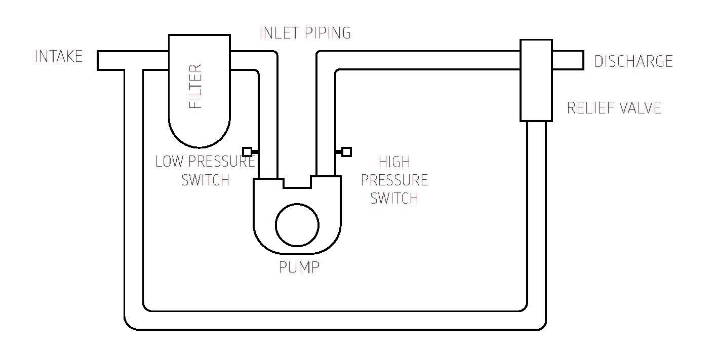
We suggest that you use the precautionary measures and piping layout that follow. This layout promotes a long, trouble-free life for your pumps.
FILTER
If particles may contaminate the fluid, use a particulate filter that is capable of filtering particles larger than 125 microns. If the particles are abrasive, use a filter that is capable of removing virtually all of the particles.
Make sure there is at least six inches of piping between the pump inlet and any “T-fitting,” elbow, or system component to minimize turbulence. The piping should be made from a material that does not corrode or shed particles. A flexible hose of plastic, copper, or stainless steel are good choices, among others. Be sure no joint compound or tape falls into the inlet of the pump.
IMPORTANT NOTICE FOR GLOBAL CUSTOMERS